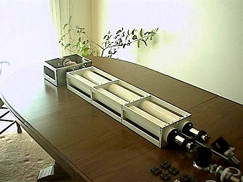
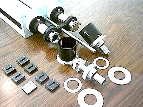
Since I have never used a SHS and have not yet had hands-on experience with their operation, this first attempt is designed as a test platform for trying different configurations of the Arcetri layout. The intent is to make this SHS such that it can be used as an accessory that can be mounted to any larger telescope that can be used to feed it sunlight. Since it is a prototype, it is built in three removable sections so that if any one section of the SHS is found to be lacking in performance, it can be quickly and easily removed and replaced with a modified section. The three sections are as follows:
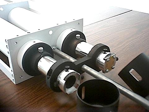
1. The main COLLIMATOR and SLIT section, which consists of a strong framework constructed of aluminum that will serve as a mounting point for the small test telescope (a 3 inch refractor), and also serves as an attachment point of the SHS to an equatorial fork mount for testing. Eventually, this SHS will be equipped with brackets for mounting to the side of a 6 inch refractor. This section holds the two tubes of the Arcetri spectroscope, and the two slits which are mounted in the two drawtubes. Focusing of the collimator lenses on the slits is accomplished by turning a single central threaded rod which simultaneously moves the two drawtubes. The slits are rapidly interchangable, and the effective focal length of the collimator lenses can be increased by the simple addition of a pair of Barlow lenses to the drawtubes. In addition, the collimator lenses are easily replaceable with larger ones if needed.
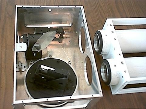
2. The GRATING section is readily attached to the collimator section with four large thumbscrews. This section contains the diffraction grating and the diagonal mirror. The diffraction grating is held in an easily replaceable cell which can be exchanged with other cells for the testing of additional gratings. These cells are held in the grating mount which is adjustable for tilt and can be quickly rotated about its axis by loosening two small thumbscrews for selecting which of the grating's orders is to be used. Once these thumbscrews are tightened, the mounts's base is held firmly to a tangent arm for fine tuning of spectral lines. The lead screw of the tangent arm is fitted with an extension rod which extends to the eyepiece end of the SHS for convenient adjustment.
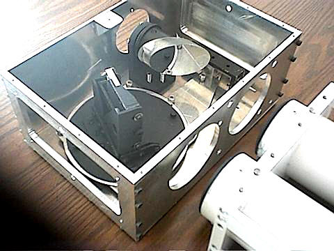
3. The INPUT/OUTPUT section will also be easily removable from the collimator section with four large thumbscrews, and will contain the image synthesizer, the input port which brings light from the telescope, and the output port which will enable mounting of a relay lens if needed, and a focuser for the eyepiece.
Since this instrument is intended to eventually be mounted to the side of an equatorially mounted telescope, vibration must be minimized. That eliminates any reciprocal motions in the synthesizer. For this reason I have shied away from using the simpler tilting-mirror synthesiser in favor of the relatively vibration free spinning Anderson prisms. The typical implementation of Anderson prisms requires horizontal slits so that both prisms can be mounted on the same motor shaft which keeps them in perfect synch. However, the Arceti spectroscope requires vertical slits. To overcome this limitation, my original intention was to use a Dove prism (an image rotator) in each of the collimator lens' light paths to twist each light path through 90 degrees so that the orientation of the slits could be horizontal. Unfortunately, the Dove prisms I acquired were of poor optical quality, which forced me to change my plan and live with the vertical slits, mounting the Anderson prisms on separate motors in the Petit arrangement. This will require precise regulation of motor speed to keep the spinning prisms in synch and will hopefully be accomplished by finely adjustable separate power supplys for each motor.
CURRENT OPTICAL COMPONENTS:
Collimator Lenses: 54mm x 1016mm f.l. Jaegers cemented coated achromats. The effective focal length is modified to approximately 1800mm by a pair of coated negative achromats of about -230mm f.l. This can be varied as desired, or modified by using any 1.25" pair of Barlow lenses.
Grating: 30mm x 30mm Edmund 1200 lines/mm 5000A blaze. I have made another cell to contain a 50mm x 50mm grating for future experiments.
Arcetri Diagonal: 2.14 inch m.a. 1/10 wave flat from University Optics.
Slits: I currently have on hand a set of eight interchangeable slit assemblies with widths from 0.001 to 0.011 inches. More can be made, or these can be modified as necessary. The blades are made from 0.015 inch brass strips with the edges stoned smooth. Parallelism of the slits is held to less than 0.0005 inches by use of a small optical comparator during assembly.
Anderson Prisms: Two pairs of 25mm r.a. prisms cemented together with Norland 61 cement. Thickness of prisms side-to-side held to 0.002 inches (after initial failure).
CURRENT MECHANICAL COMPONENTS:
Petit motors: Small high-torque DC gear motors that operate smoothly from about 2 volts to about 20 volts. They seem happiest between about 6 and 12 volts, where they provide about 300 to 600 RPM (if I remember correctly). Each motor will be powered by an LM317 adjustable voltage regulator. One regulator will be provided with a 10-turn potentiometer for precise matching of speed to the other. Although only one is needed, both motor mounts can be proveded with independant rotation adjustment to counteract synchronization drift. (I hope this works!)
Grating Movement: 6.5 inch tangent arm driven by 32 TPI lead screw in ball bearings with anti-backlash spring.
Questions or comments: jsstars@worldnet.att.net
Jim's Q: Has
anyone tried using a large, dense flint equilateral prism
placed downstream (or up stream) from their grating to increase
dispersion? This would NOT increase resolution of the grating, but
would it effectively increase the linear width of spectral lines at
the exit slit to advantage? Would this enable one to use shorter
focal length spectroscope lenses/mirrors for the same effect of long
ones?
Fred's Response:
a prism can be used
with a grating, but it complicates
the set up, stick just with a grating. A prism can curve the spectral
lines a bit.
Here is a progress report on my SHS project
for those that are
interested.
I have posted three more photos on the YahooGroups SHS site in
the Photos section under PlanetMan/ArcetriPetit.
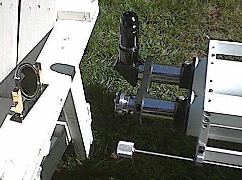
Yesterday I completed the grating box and assembled it to the
collimator assembly. To get an idea of the spectroscopic resolution,
this morning I took the spectroscope outside and set it on a lawn
chair and reflected sunlight onto the slit with the polished
stainless steel back of a desk clock. To use it as a spectroscope I
put a 40mm Kellner eyepiece and a star diagonal in the tube where the
exit slit will be mounted when this will be used in SHS mode (see
photo 1stSpec.jpg).
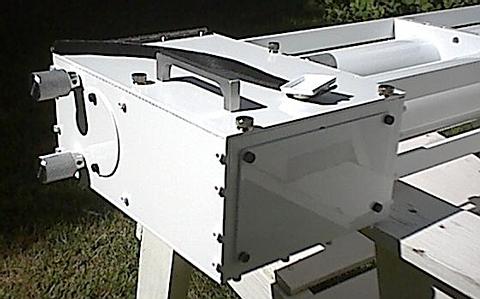
The photo GratDust.jpg shows the finished grating box. On top of
the box is the little white protective cover that came with the
grating. I glued this cover to a Velcro strap. When the grating is
not in use the strap wraps around the grating mount and holds the
cover in place to keep the grating clean and protected.
Here are the morning's experiences that I thought I would share
with the group (and thereby show my newness and lack of knowledge
about solar spectroscopy - but I'm learning!):
I was pleasantly surprised to see the spectral resolution of
this thing. It is tremendously better than my little benchtop
spectrometer with a flint prism! Yay!! :)
With a 0.003" slit the D2 line of the sodium pair would not
quite show its faint companion.
With a 0.002" slit the D2 line was easily seen to be double and
I could easily see 7 faint lines between the D1 and D2 sodium lines
and suspected two more.
With a 0.001" slit I could easily see 9 faint lines between D1
and D2 and could tell that there were two more just past the
resolving power. I see now that I am going to have to make some
narrower slits, though at 0.001" the brightness falls off quite a
bit. I suspect brightness will not be as big a problem though, when
light from a telescope will be focused on the slit instead of the
feeble light reflected from the back of a metal clock.
I was surprised also by how wide the H-a line is. When I first
saw how narrow the dark sodium lines are, I was a little worried
about not being able to keep only the H-a light on the exit slit when
in SHS mode, but the H-a line is wide and should not be a problem.
It was disappointing to see how much brightness is lost when
tuned to the H-a line too. As Fred told us, not only does the 5000A
grating efficiency drop off a lot in red light, but so does the
efficiency of the eye. I can see now that my next grating will
probably be one blazed nearer to 6000A.
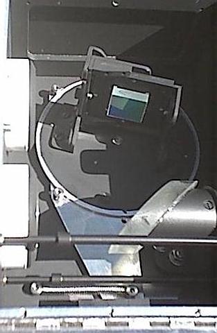
If you look at the photo GratObliq.jpg you can see the extremely
oblique angle the grating makes to the lens of the exit tube in the
Arcetri arrangement. This results in the grating appearing very
narrow from the point of view of the exit slit. I wonder if this has
any effect on brightness, efficiency, or resolution? Perhaps not
since all light is reflected. Even if foreshortened, all the light is
still present, right?
I wonder though, if moving the grating back a few inches from
the second achromat and tilting the diagonal mirror appropriately
would improve any losses by making the angle less oblique. Thoughts
anyone?
I was also a bit disappointed by the loss of brightness and
image quality when using a cheap pair of Barlow lenses in each tube
to extend the focal length. On the optical bench with an illuminated
target the image looked very good, but in the real world it made me
frown a bit, though I will need to experiment some more when I get
the synthesizer finished and feed real telescope light into it. I did
not get a chance to try out the better pair of negative achromats I
have though. Perhaps they will work better.
All in all, I have a good feeling about the SHS so far. I am
happy that I have finally taken a baby step and received a tiny bit
of firsthand experience. :)
I also felt the first tugs of a new fever. I suspect it is
called something like "dispersion fever" or "grating fever" - a
cousin to "aperture fever". When I look at that tiny little 30mm
grating at the far end of the collimator tube and imagine what a 50mm
or 70mm would do... ;) But I must resist.
- Jim
Hi Jim,
Nice work. It's was a real thrill when I saw my first solar spectrum
with my Arcetri spectroscope. If think the H-alpha line is thick, take a
look at the the Calcium lines. One soon understands why you need a very
narrow slit opening when using other lines besides the H-alpha. When I
saw your grating box I noticed that the lens are fairly close to the
grating and I did not see a baffle that would divide the box in half. When
your using the first order, it possible that the second and third order
spectrum will be reflecting into the lens in front of the 45 degree flat
and lowering the contrast.
In my Arcetri unit I placed the lens about 12" behind the flat and
grating and the lens cell extends a few inches in front of the lens so it
shields the lens from any reflected light either coming from the grating or
the 45 degree flat.
Best Regards,
Dave
> When
> your using the first order, it possible that the second and third
order
> spectrum will be reflecting into the lens in front of the 45 degree
flat
> and lowering the contrast.
Hi David,
Thanks for the tip! I didn't think of the second order spectrum
path. I'll have to add a baffle as you suggest.
Thanks again!
- Jim
Hi Jim,
For the spectroscope mode, entrance slit about .0005 is best (12 microns), exactly so is not critical, so do not go nuts on exact this or that. But the .001 slit is acceptable (25 microns).
Your grating and folding diagonal are about 90 deg angles to each other and the two achromats. There is a lot of foreshortening of the grating at the red of the spectrum. I do not know exactly if there will be a problem. So try out your present set up and see how it goes.
You might have to set back the grating several inches. The angle between the grating and the diagonal will be different, but the foreshortening of the grating for the red of the spectrum will be less. In my book I have one drawing with the correct angles, about page 100, as done in Italy, Florence observatory. The book THE SUN by Abetti has it that way. In the rear of the book there are other drawings with 90 deg angles. That is my error. Sorry.
Hi Fred,
Yes, the difference in resolution between 0.002" and 0.001"
slits was very apparent. I will make a 0.0005" slit sometime in the
near future. I'm sure it will result in even better resolution. I
don't think I'll try to make one smaller than that though. Once you
get down to 0.001" things get VERY touchy and I doubt my ability to
make one smaller than 0.0005".
As for the foreshortening of the grating in the red, when I get
my synthesizer done I will try the grating in its current position,
and then I will move the diagonal forward and see if there is a
difference in performance. It should be a simple task to move the
diagonal forward by reversing the L-bracket it is mounted to. That
will buy about 2 inches or roughly 20 degrees of grating tilt.
I will be sure to report the results.
My current thinking is that the foreshortening will not be an
issue though, since the grating is effectively a mirror which
reflects all the light that strikes it, so none is really lost by the
foreshortening. I may be wrong though. Gratings are still pretty
mysterious to me. But I will be sure to report on what I find.
Good seeing!
- Jim
Hi,
You got to have separate, enclosed light paths for each lens for the Arcetri design.Have a light baffle up near the grating so that spectrum will not reflect in the wrong directions. Keep out wild scattered light from going down into the eyepiece and into the eye, can lower the constrast of the spectrum in spec mode, and solar disk in SHS mode. Cheers, Fred
Hi Jim, Aug 8, 2002
In the rear pages of my 119 page book, there is some discusson on gratings. I keep it as simple as possible. Please read and study the importance of those pages. It takes some of the msystery out of gratings.There are three concepts to learn,
angular dispersion
linear disperson
grating resolution
The formulae are there, also examples.You do not have to be an expert to learn some basics.I am not king in the field of math, I just know lots of basics, that is all.
A slit .001 inch (25 microns) is not too difficult, anything narrower is not easy. If you get about .0005(12 microns), plus or minus about .0001 inch, that will be great.
Since 1962 in regards to SHS, about 40 to be exact, i had tried various design, make all kinds of calculations, read all kinds of book and journals, whatever, and I do not know it all.About 90% of my book is mine, the rest is contributions from other amateurs.So if you can fill in a gap of knowledge, it will be great, and you will be given credit for it too. Fred